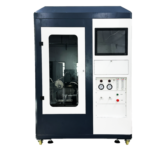
Building Materials Ignitability Tester G6172
Category:Material combustion tester
Introduction
1.Scope of Application:
This apparatus is suitable for testing the ignitability of materials, composite materials, or assemblies with a thickness not exceeding 70 mm when placed horizontally and exposed to specified thermal radiation conditions.
It can be used to evaluate wall and ceiling lining materials, flooring systems, external claddings, and insulation materials for air-heating ducts. Under specific fire scenarios, the test accurately describes the fire exposure behavior of products. Therefore, the results reflect the combustion performance of products in actual use.
Through testing, materials that are easily ignited and those that are difficult to ignite can be distinguished, helping to classify the fire hazard level of materials.
2. Complies with Standards:
2.1 GB/T 14523-2007 Test Method for Ignitability of Building Materials
2.2 ISO 5657:1997 Reaction to Fire Tests — Ignitability of Building Products
3. Main Advantages:
3.1 Advanced Control System
The control system adopts PLC programming, computer control, high-precision data acquisition boards, modular control, and PID control. Signal acquisition and processing use a 16-bit high-precision board, achieving accuracy up to 1%. The system offers stable performance and excellent repeatability.
3.2 Computer Control Interface
Professional testing software developed based on LabVIEW is used. The interface is rigorous and highly automated. All complex procedures and calculations are integrated into the computer system, ensuring fast response, convenient operation, and a user-friendly interface. During the test, real-time data monitoring is available. Automatic data acquisition, processing, storage, and output of test results are supported.
3.3 Operating Software
Windows XP operating interface with LabVIEW style design. Easy operation with a user-friendly and simplified control interface.
3.4 Air and Propane Supply System
Air and propane are supplied to the ignition flame through regulating valves, filters, flow meters, check valves, and a flame arrestor. High-precision mass flow controllers are used to accurately control the flow of propane and air supplied to the ignition flame.
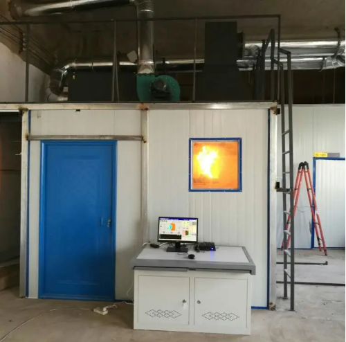
3.5 Environmental Control Design
In accordance with Section 8 of GB/T 14523-2007 and Section 8 of ISO 5657:1997, the test shall be conducted in an environment with minimal air movement or protected from drafts. The air velocity around the apparatus shall not exceed 0.2 m/s. Operators should avoid exposure to combustion products. Released smoke must be extracted without creating forced ventilation above the apparatus.
Accordingly, a specially designed enclosure ensures that airflow does not affect the test while effectively exhausting smoke.
4. Main Performance Parameters:
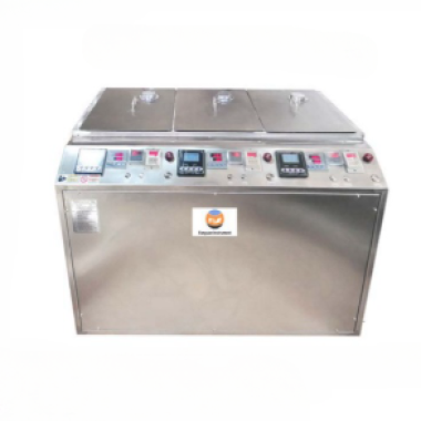
4.1 Complete unit: Composed of a radiation cone, ignition device, nozzle, pressing plate mechanism and support frame, temperature recorder, gas system, signal acquisition and processing system, computer, etc.
4.2 Specimen Support Frame, Shield Plate, and Pressing Plate:
4.2.1 The specimen support frame and other components of the fixing device are made of stainless steel. The support frame is constructed from square steel tubes with a wall thickness of 1.5 mm and dimensions of 25 mm × 25 mm. The overall dimensions are 275 mm × 230 mm.
4.2.2 The horizontal shield plate has a side length of 220 mm and a thickness of 4 mm. It is fixed 260 mm directly above the base frame by four legs with a diameter of 16 mm installed at the corners of the shield plate. A circular opening with a diameter of 150 mm is cut in the center of the shield plate. The upper edge of the opening is chamfered at an angle of 45° to the horizontal plane, with a width of 4 mm.
4.2.3 Two vertical steel guide rods with a length of less than 355 mm and a diameter of 20 mm are installed on the frame, positioned at the midpoint of each short side of the support frame. Beneath the shield plate, a 25 mm × 25 mm horizontal adjustment rod is installed between the two vertical guide rods. The adjustment rod can slide along the guide rods and can also be manually fixed at a certain position by screws. A vertical sleeve hole is located at the center of the adjustment rod to secure a vertical sliding rod with a diameter of 12 mm and a length of 148 mm. The sliding rod supports a square pressing plate with a side length of 180 mm and a thickness of 4 mm. The pressing plate is pushed against the lower surface of the shield plate by a balanced rotating arm, which is mounted below the horizontal adjustment rod and presses against the bottom end of the vertical sliding rod.
4.2.4 One end of the rotating arm is equipped with a roller that contacts the hub at the lower end of the vertical sliding rod, while the other end is fitted with an adjustable counterweight. The counterweight
balances specimens of different masses and applies a constant pressure of 20 N between the specimen and the shield plate. During the test, as the specimen may collapse, soften, or melt, an adjustable
positioning device is provided to limit the upward movement of the pressing plate to a maximum distance of 5 mm. Spacers may be optionally used between the pressing plate and the shield plate.
4.3 Radiation Cone
Figure 4: Radiation Cone
4.3.1 Radiation Cone:
Rated power: 3 kW. Radiant intensity: 10 kW/m²–70 kW/m². The heating element consists of a 3500 mm long, 8.5 mm diameter stainless steel electric heating tube, wound into a truncated cone shape and installed inside a protective casing.
The overall height of the casing is (75 ±1) mm, with a top inner diameter of (66 ±1) mm and a bottom inner diameter of (200 ±3) mm. The protective casing is made of 1 mm thick stainless steel on both inner and outer layers, with 10 mm thick ceramic fiber insulation material (nominal density 100 kg/m³) sandwiched in between.
The heating element is firmly fixed to the inner surface of the protective casing with steel pins. Four equally spaced clamps are used around the circumference to prevent accidental loosening of the heating tube at the bottom. When projected vertically, the wound heating element does not obstruct more than 10% of the opening area at the top of the protective casing.
4.3.2 At the center of the shield plate opening or on a reference plane coinciding with the lower surface of the shield plate, the radiation cone can produce a radiant heat flux of 10 kW/m²–70 kW/m².
4.3.3 On the reference plane, the radiation intensity distribution provided by the radiation cone meets the following requirements:
Within a circular area of 50 mm diameter inside the shield plate opening, the deviation between the radiant intensity and the central radiant intensity does not exceed ±3%.
Within a circular area of 100 mm diameter, the deviation does not exceed ±5%.
4.3.4 The radiation cone is fixed by clamps onto the lifting guide rod on the specimen support frame. The lower edge of the radiation cone protective casing is positioned (22 ±1) mm above the surface of the shield plate.
4.3.5 Thermocouples: K-type armored thermocouples are used. The thermocouple in close contact with the heating tube (main thermocouple) controls the heating temperature of the radiation cone. A second thermocouple (auxiliary thermocouple) is installed in a similar manner at a position diametrically opposite the main thermocouple.
Each thermocouple is fixed to the coiled heating tube and positioned within 1/3 to 1/2 of the height of the radiation cone below the top surface. The sensing junction (within 8 mm from the end) is located in a region of approximately uniform temperature.
4.4 Ignition Mechanism:
4.4.1 The ignition mechanism consists of an ignition arm, a pilot ignition source, and cams.
4.4.2 The ignition flame is discharged from a stainless steel nozzle installed at the end of the ignition tube.
4.4.3 The ignition flame is positioned above the radiation cone, where smoke plume and pyrolysis products emerge from the top surface. When positioned there, the ignition nozzle is located near a pilot ignition source with a heat output not exceeding 50 W, capable of repeatedly re-igniting the ignition flame.
The propane flame is discharged from a nozzle with an inner diameter of 1 mm–2 mm, producing a flame length of 15 mm and a heat output of approximately 50 W.
4.4.4 The ignition flame is positioned above the center of the shield plate opening. The flame is discharged horizontally and perpendicular to the movement direction of the ignition arm. The center of the nozzle orifice is located (10 ± ) mm above the shield plate.
4.4.5 The ignition mechanism is equipped with a limit cam and a drive cam, allowing the lowest position reached by the ignition flame during operation to be fixed at any position between 20 mm above the test position and 60 mm below the test position.
4.4.6 Ignition Device:High-voltage automatic electronic ignition. Automatically moves to the test position and automatically retracts.
4.4.7 Drive Method:Driven by a stepper motor and ball screw mechanism.
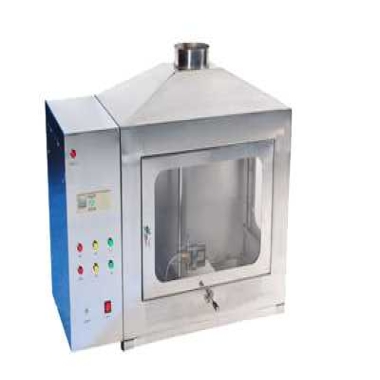
4.5 Specimen Cover Plate
4.5.1 The specimen cover plate operates automatically (opening and closing). The computer sends signals to complete the action.
4.5.2 The cover plate is made of 2 mm thick SUS304 stainless steel, capable of covering the shield plate. A limit device prevents contact with the shield plate. A handle is provided for convenient removal.
4.6 Temperature Monitoring System
4.6.1 Radiation Cone Temperature Controller:
Uses a temperature module, PLC program, and PID control. Equipped with an Advantech temperature module and Delta PLC.
4.6.2 Temperature Control:
SCR (silicon-controlled rectifier) output control is adopted, providing a maximum output current not less than 15 A. Heater temperature control resolution: ±1°C. Temperature range: 0°C–1000°C.
4.7 Radiometer (Heat Flux Meter)
4.7.1 Imported military-grade thermopile heat flux sensor, Gardon type, Hukseflux (Netherlands). Measurement range: 0 kW/m²–100 kW/m².
4.7.2 Accuracy: ±3%, Repeatability: 0.5%, Resolution: 0.1 kW/m²
4.7.3 Voltage Measurement Device:
High-precision voltage signal amplifier matched with the radiometer output. Its full-scale deviation, sensitivity, and accuracy enable a display resolution of 0.1 kW/m² for radiant heat flux.
4.7.4 Equipped with a portable water-cooling system.
4.8 Timer: Resolution: 0.01 s, Accuracy: 1 s/h
4.9 Air and Propane Supply System:
Air and propane are supplied to the ignition flame through regulating valves, filters, flow meters, check valves, and flame arrestors.
4.9.1 Gas Regulating Valve:
Adjusts the pressure and flow rate of propane and air supplied for ignition. Propane can be adjusted to 19 mL/min–20 mL/min, and air flow can be adjusted to 160 mL/min–180 mL/min.
Figure 5: Imported Heat Flux Meter
4.9.2 Filter:
Removes impurities (such as oil droplets) carried in the gas pipeline to prevent interference with the flow meter readings.
4.9.3 Flow Meter:
Measures the flow rate of propane and air supplied to the ignition flame. Accuracy: 3%.
4.10 Balance:
Capacity: 5000 g
Indication accuracy: 0.1 g
4.11 Control System:
Adopts PLC programming, human-machine interface (HMI), and computer control. The software uses dedicated instrument development software LabVIEW and a data acquisition control card. During the test, real-time test data can be monitored, and automatic data acquisition, processing, storage, and output of test results can be achieved.