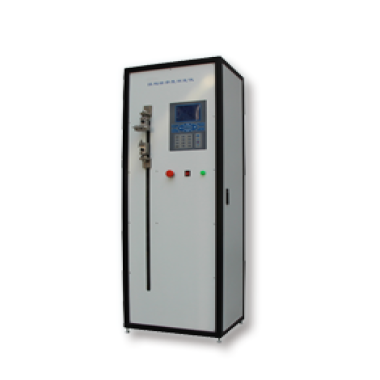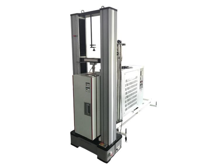
High-Temperature Creep Testing Machine(10KN)
Category:Universal Strength Tester
Introduction
1. Manufacturing and Inspection Standards
GB/T 16491 Electronic Universal Testing Machine
GB/T 2611 General Technical Requirements for Testing Machines
GB/T 6825.1 Verification of Static Uniaxial Testing Machines – Part 1: Verification and Calibration of the Force Measuring System of Tension and/or Compression Testing Machines
2. Applicable Test Method Standards
ASTM D 2990 Standard Test Methods forTensile, Compressive, and Flexural Creep and Creep-Rupture of Plastics1
GB 11546.1-2008 Plastics — Determination of Creep Properties — Part 1: Tensile Creep
GB/T 15048-94 Rigid Cellular Plastics — Test Method for Compressive Creep
GB/T 20672-2006 Rigid Cellular Plastics — Determination of Compressive Creep under Specified Load and Temperature Conditions
GB/T 1040.1-2006 Plastics — Determination of Tensile Properties — Part 1
GB/T 1041-92 Test Method for Compressive Properties of Plastics
GB/T 9341-2000 Test Method for Flexural Properties of Plastics
3. Application Range
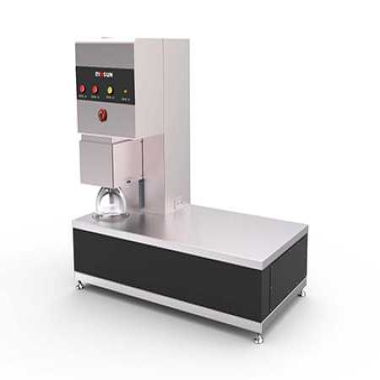
The testing machine is mainly used for creep, stress relaxation, tensile, compression, bending, shear, peel, and tear testing of non-metallic materials.
4. Main Technical Specifications
4.1 Test Force
Maximum test force (kN): 10
Effective measuring range: 0.4%–100% FS (single range, no internal division)
Resolution: 1/300000
Relative indication error: ±0.5%
4.2 Test Speed
Speed adjustment range: 0.05–500 mm/min (stepless speed regulation)
Speed relative error: ±0.5%
Constant test force rate and constant deformation rate control range: 0.01%–5% FS/s
Constant test force rate and deformation rate control error: ±0.5%
Constant test force and constant deformation control range: 0.5%–100% FS
Constant test force and constant deformation control error:
Less than 10% FS: ±1% of the set value
Greater than 10% FS: ±0.1% of the set value
4.3 Displacement (Moving Crosshead)
Measurement range: 0–999 mm
Resolution: 0.001 mm
Relative indication error: ±0.5%
4.4 Deformation
Crosshead deformation measurement accuracy: ±0.5%
Crosshead deformation measurement range during test: 860 mm
Large deformation measurement accuracy: ±0.5%
Large deformation measurement range: 25–1000 mm
5. Main Frame and Accessories
| Model | 10 kN |
| Maximum Test Force | 10 kN |
| Effective Test Width | 420 mm |
| Maximum Travel of Moving Crosshead | 1160 mm |
| Main Frame Dimensions (L × W × H) | 900 × 480 × 1810 mm |
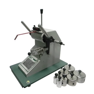
| Maximum Clamping Force of Wedge Grips | 10 kN |
| Clamping Range (Flat Specimen) | 0–8 mm |
| Clamping Range (Round Specimen) | Φ6–Φ16 mm |
| Compression Device | Φ70 mm |
| Bending Device Support Roller Radius | R2.5 / R5.0 mm |
| Pressure Roller Diameter | Φ5 mm |
| Span Range | 120 mm |
| Power Supply | 220 V, 50 Hz, 0.4 kW |
| Weight | 280 kg |
6. Structural Principle and Performance Features
The computer-controlled electronic universal testing machine mainly consists of the main frame, fully digital measurement system (load, displacement, deformation), servo system, computer control system with software package, and functional accessories.
6.1 Main Frame
The upper crosshead and the worktable are connected by four columns forming a portal-frame structure. A transmission mechanism is installed at the bottom of the worktable.
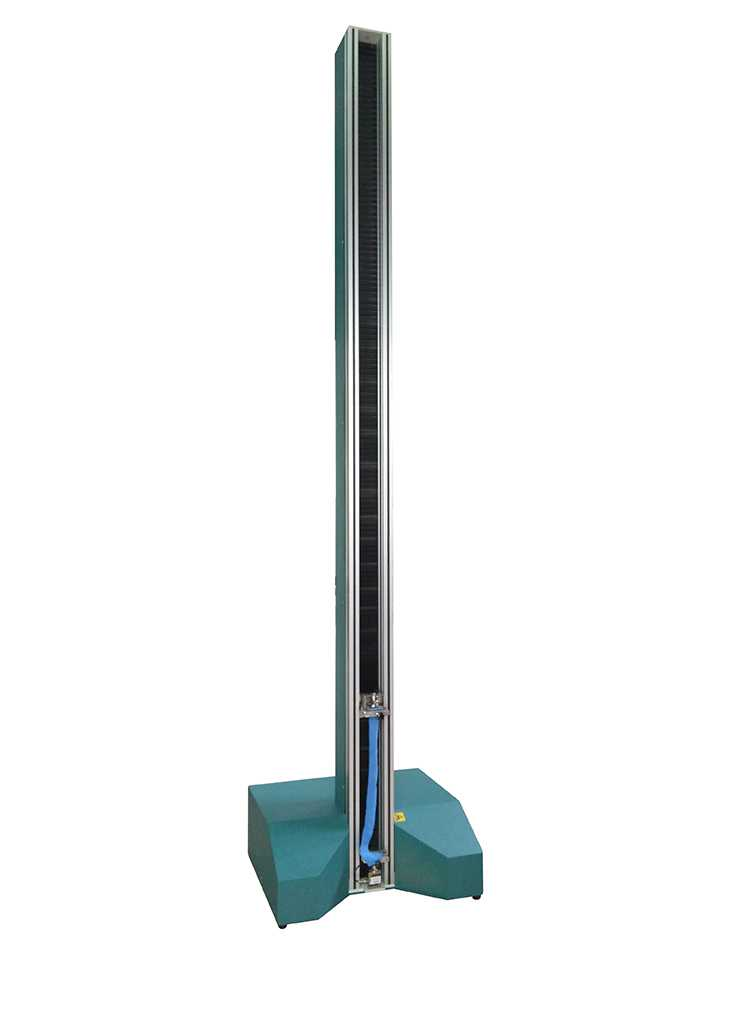
The transmission of the AC servo motor is reduced through a three-stage circular synchronous belt pulley system, which drives the ball screw to rotate and move the crosshead up and down. In addition to the ball screw guidance, guide columns also provide guidance for the moving crosshead. Thus, the simply supported beam structure of the moving crosshead becomes a fixed beam structure, increasing the rigidity by nearly three times.
The circular synchronous belt pulley and ball screw pair provide stable backlash-free transmission, enabling precise control of test force and deformation speed.
A photoelectric encoder is installed at the upper end of the screw for displacement detection of the moving crosshead. A limit mechanism is installed on the left cover plate to limit the movement range of the moving crosshead.
Speed control adopts an imported fully digital AC servo system. Through high-precision feedback, a full closed-loop control is formed. The system features a wide speed regulation range, fast response, and short positioning time. It also provides test force and deformation rate control functions.
The worktable, moving crosshead, and upper crosshead are all manufactured from high-quality steel plates through precision machining, which reduces vibration when the specimen fractures and improves overall rigidity.
7.Main Frame Features
(1) 1.1 The main frame adopts a portal-type prestressed structure with high rigidity, minimizing the influence of machine deformation on test results.
(2) 1.2 Circular synchronous belt pulley reduction and ball screw pair transmission are used to achieve backlash-free transmission, ensuring precise control of test force and deformation speed.
(3) 1.3 Stable transmission, fast response, and low noise.
(4) 1.4 Photoelectric encoder displacement sensor with high resolution and strong anti-interference capability.
(5) 1.5 Displacement protection system ensuring safe and reliable operation.
(6) 1.6 During assembly of the main frame and grips, strict control and adjustment are applied to ensure the coaxiality between the center hole of the load sensor on the moving crosshead and the positioning hole of the grip seat, as well as the coaxiality between the grip mounting shaft and the jaws. This ensures that the force application axis of the grips coincides with that of the testing machine, with an error controlled below 9%, which is far lower than the requirement of Grade 0.5 accuracy specified in GB/T 16491.
(7) Therefore:
a) Bending stress caused by eccentric loading is minimized, improving the force condition of the specimen so that it receives uniform axial force, making the force-displacement curve more accurate.
b) Errors in force and deformation measurement caused by eccentric force are eliminated.
(8) Imported fully digital servo system with the following features:
a) Resonance suppression and control function to achieve high-speed positioning.
b) Full closed-loop control through high-precision feedback to improve system accuracy.
c) Speed frequency response up to 500 Hz, enabling fast speed response and short positioning time.
d) Wide speed regulation range.
8. Fully Digital Measurement and Control System
The measurement controller, together with the servo system, load cell, extensometer, and displacement sensor, forms a fully digital measurement and control system.
8.1 Measurement Controller
The measurement controller is a new type of measurement and control device integrating data acquisition, data processing, and process control. It adopts the most advanced SOC (System on Chip) technology and DSP (Digital Signal Processing) technology based on FPGA (Field Programmable Gate Array) architecture.
FAQ
1.What is a High-Temperature Creep Testing Machine?
A High-Temperature Creep Testing Machine is an advanced apparatus designed to measure the creep properties of materials at elevated temperatures. Creep is the gradual deformation of materials under constant stress, which can lead to failure over time. These machines typically utilize controlled heating elements and precise load application systems to conduct experiments, allowing researchers and engineers to assess how materials behave under high-temperature conditions.
2.What materials can be tested with a High-Temperature Creep Testing Machine?
High-Temperature Creep Testing Machines can test a variety of materials, including metals, alloys, ceramics, and composites. Common testing materials include nickel-based superalloys, titanium alloys, and certain polymers that are designed for high-temperature applications. The choice of material often depends on the specific industry requirements, such as aerospace, automotive, or energy production, where performance under high stress and temperature is critical.
3.Why is creep testing important?
Creep testing is crucial in industries where materials are subjected to high temperatures and loads for extended periods. Understanding the creep behavior of materials helps predict long-term performance, service life, and failure mechanisms. This information is vital for the design and safety of components in applications like turbine engines, pressure vessels, and nuclear reactors, ensuring they can withstand operational stresses without compromising safety.
4.How is a high-temperature creep test conducted?
A high-temperature creep test starts with specimen preparation, where a standardized sample is machined to specific dimensions. The specimen is then placed in the testing machine, which heats it to the desired temperature. A constant load is applied, and the deformation is measured over time, typically using extensometers or other measurement devices. The test continues until either a predefined time limit is reached or the specimen fails, yielding data on the material’s creep rate.
5.What are the key parameters measured during creep testing?
During creep testing, several key parameters are measured, including the creep strain rate, total creep strain, and time to rupture. The data collected helps to construct creep curves that depict the relationship between stress, strain, and time. Additional parameters like temperature and applied load are also recorded to analyze the material’s performance in various conditions, which is crucial for accurate material characterization.
6.What industries benefit from High-Temperature Creep Testing?
Several industries benefit from high-temperature creep testing, including aerospace, power generation, automotive, and petrochemical industries. In aerospace, it ensures components can withstand the extreme conditions of flight. In power generation, it helps evaluate materials used in turbines and reactors. Similarly, the automotive industry uses creep testing to validate components that operate at high temperatures, ensuring safety and reliability in vehicle performance.