Mechanical Load Testing Machine
Category:Other Aging Machines

Introduction
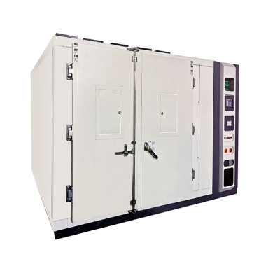
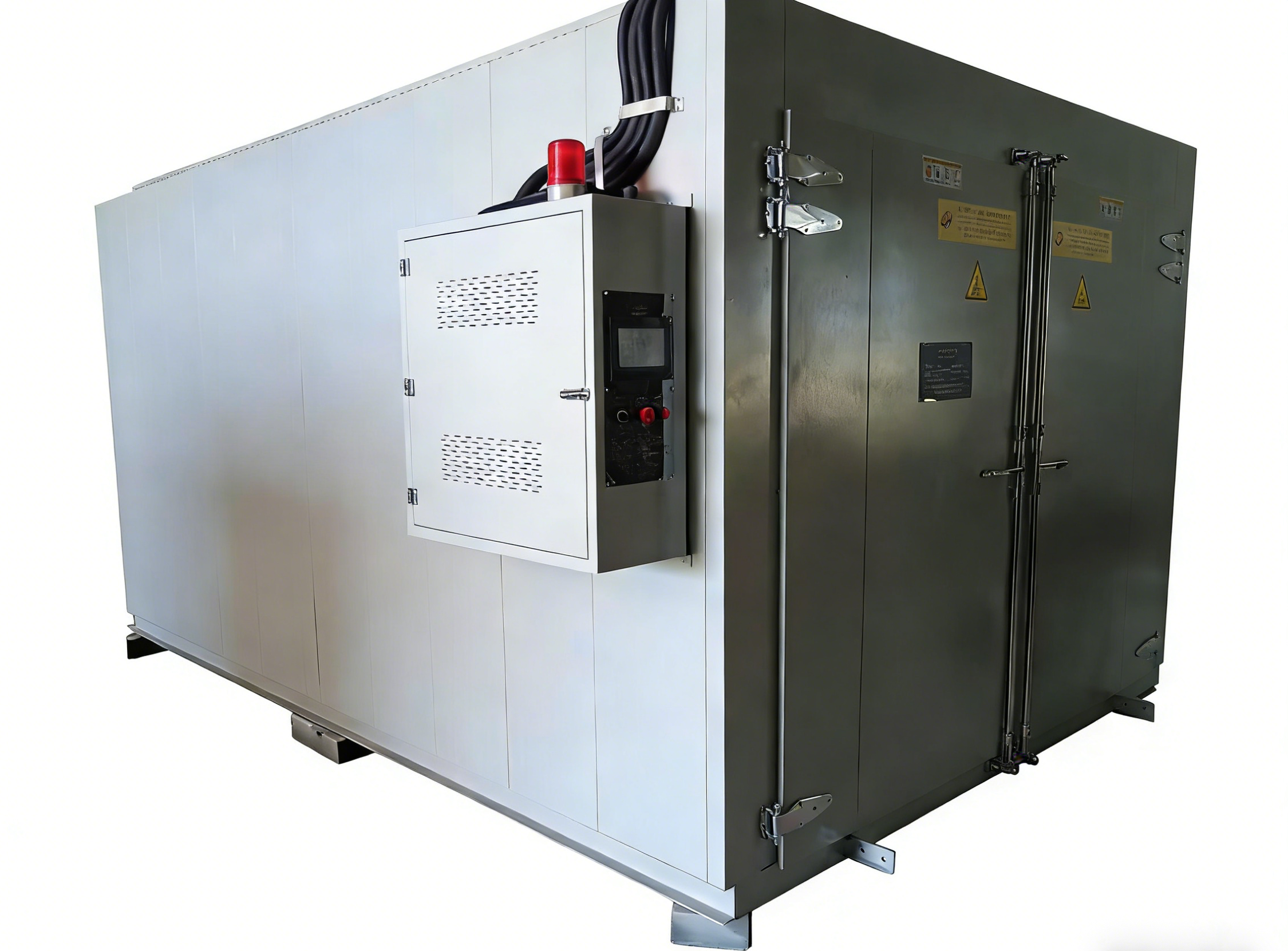
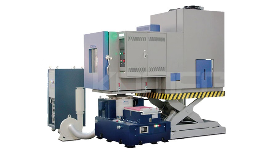
The Mechanical Load Testing Machine is a precision instrument designed to evaluate the mechanical load-bearing capacity of photovoltaic (PV) modules under static and dynamic conditions. It simulates wind, snow, and ice loads through dynamic pressure technology, providing reliable assessment of module structural integrity, compressive strength, and deformation resistance. The machine ensures PV modules perform safely and stably in real-world environmental conditions.
Application
The machine is widely used for mechanical performance testing and structural verification of PV modules and related components:
Photovoltaic Module Load Testing: Static and dynamic load evaluation.
Wind and Snow Simulation: Verification under simulated wind pressure, snow load, and ice accumulation.
Structural Reliability Assessment: Testing mounting system durability.
Compressive and Deformation Resistance: Evaluating module resilience under mechanical stress.
Electrical Continuity Monitoring: Real-time detection of current continuity and short-circuit protection.
Standardized Laboratory Testing: For PV module certification and quality control.
Module Certification Tests: Compliance with IEC 61215. IEC 61646. UL 1703. IEC 62782 standards.
Standards
The machine is designed to meet key international and domestic PV module mechanical testing standards:
GB/T 9535 series – Mechanical Load Testing of Photovoltaic Modules
IEC 61215 – Crystalline Silicon Photovoltaic Module Design Qualification and Type Approval
IEC 61646 – Thin-Film Photovoltaic Module Design Qualification
IEC 62782 – Mechanical Load Testing for PV Modules under Snow and Wind
UL 1703 – Safety Standard for Photovoltaic Modules
Parameters
| Item | Technical Parameter |
|---|---|
| Machine Dimensions | L 280 × D 180 × H 195 cm |
| Forward Load | 5400 Pa (adjustable) |
| Reverse Load | 2400 Pa (adjustable) |
| Cycle Count | Programmable |
| Dynamic Load Frequency | 7 s ±3 s |
| Dynamic Load | 1000 Pa × 1000 cycles |
| Pressure Control Accuracy | ±5% |
| Force System | Low-friction cylinder + tension/compression sensor (0.1 N accuracy) |
| Frame Material | Aluminum profile structure with electrophoretic surface treatment |
| Max Test Size | 2000 × 1000 mm (customizable) |
| Custom Fixtures | Adjustable according to module installation |
| Electrical Continuity System | DC 150 V / 2 A, real-time monitoring |
| Number of Cylinders | 8 (4 sets × 2) |
| Cylinder Force per Set | >200 kg |
| Cylinder Stroke | 150 mm |
| Suction Cups | 32 (8 sets × 4) |
| Suction Cup Diameter | 120 mm |
| Suction Cup Spacing | ≤200 mm (horizontal/vertical) |
| Suction Cup Joint Rotation | ≥15° |
Features
Low-friction cylinders combined with high-precision force sensors ensure accurate and repeatable loading.
Grouped cylinder and suction cup design allows simulation of varied load combinations and dynamic cycles.
Aluminum profile frame provides uniform force distribution, with corrosion-resistant electrophoretic treatment.
Supports testing PV modules up to 2000×1000 mm; custom sizes available.
Customizable fixtures adapt to different module mounting configurations.
Electrical continuity system monitors module circuitry in real-time.
Mature upper computer software with user-friendly interface, supporting Chinese (simplified/traditional) and English.
Real-time display of pressure, deformation, cycle count, force, and electrical continuity.
Automatic pressure stabilization and continuous data logging.
Test reports can be exported in Word, Excel, PDF, or JPG formats.
Fault warning system provides immediate alerts and operational guidance.
Accessories
Main Machine: Cylinder load system, suction cups, aluminum profile frame.
Upper Computer Software: Real-time control and data acquisition, multilingual interface.
Custom Fixtures: Adjustable for module size and mounting method.
Electrical Continuity Monitoring System: DC 150V / 2A, real-time circuit monitoring.
Force Sensor: Tension/compression sensor with 0.1 N accuracy.
Optional: Pressure calibration kit for periodic calibration of cylinders and sensors.
Maintenance Information
Verify grounding and electrical connections before each test.
Inspect custom fixtures and suction cups for wear or damage.
Regularly clean the aluminum frame and maintain electrophoretic surface integrity.
Calibrate cylinders and force sensors periodically to ensure measurement precision.
Ensure the electrical continuity monitoring system functions correctly.
FAQ
What types of loads can the machine simulate?
The machine can simulate forward and reverse static loads as well as dynamic loads that replicate wind, snow, and ice conditions. Dynamic pressure technology ensures realistic stress distribution, allowing evaluation of PV module deformation, compressive strength, and structural reliability.
How does the machine monitor electrical continuity during testing?
The electrical continuity system operates at DC 150V / 2A, continuously monitoring the module’s internal circuit. If any disconnection or short occurs, the system alerts the operator, ensuring the module remains electrically intact during mechanical load testing.
Can the machine test different PV module sizes?
Yes, standard testing supports modules up to 2000×1000 mm. Custom fixtures and optional adjustments allow larger modules or non-standard mounting configurations to be tested, ensuring versatility for R&D and certification labs.
What are the advantages of the cylinder and force sensor system?
The low-friction cylinder combined with high-precision force sensors guarantees consistent load application and measurement. This system allows accurate simulation of static and dynamic conditions, ensures repeatable results, and provides real-time force and deformation data. The grouped cylinder and suction cup design can emulate various load combinations for more realistic testing scenarios.
How should samples be installed before testing?
Samples must be fixed securely in the custom fixtures, ensuring uniform force distribution. Connect the electrical continuity system to monitor module circuitry. Proper installation prevents slippage or uneven loading during dynamic and static testing cycles.
If you're ready to take the next step, Leave your message below and we’ll reply soon. 20+ years of manufacturing & export experience, a partner you can trust.