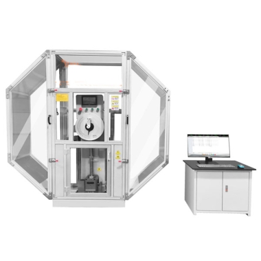
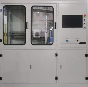
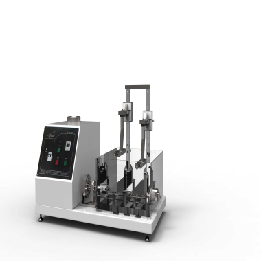
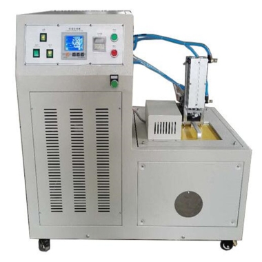
Pendulum impact tester
News 4 8 月, 2025
Pendulum impact tester
Pendulum impact testers, particularly those equipped with computer-controlled automated testing capabilities, are typically capable of accurately performing impact tests on a wide range of materials, including but not limited to plastic films, sheets, composite films, and metal foils. These devices are designed to comply with various domestic and international testing standards, including GB/T 8809, ensuring accurate and reliable test results.
Testing Principle
The pendulum impact tester’s testing principle is based on the law of conservation of momentum. When a punch of a certain mass strikes a film specimen at a certain velocity, the punch gradually decelerates due to resistance, while the film specimen deforms and cracks due to the impact. The energy dissipated by the punch can be calculated by measuring the initial and final velocities of the punch. The impact resistance of the film specimen can also be assessed by observing its deformation and cracking.
Operation method
Preparing the Specimen
Select the film specimen to be tested, ensuring that its surface is flat and free of defects such as scratches and bubbles. To ensure accurate test results, select specimens of the same thickness and material for comparison.
Installing the Specimen
Place the film specimen in the specimen holder of the pendulum impact tester, ensuring that the specimen surface is parallel to the punch surface and free of any twisting or bending.
1. Setting the Impact Speed
Set an appropriate impact speed based on the experimental requirements. Generally, a higher impact speed results in a more likely fracture. However, excessively high impact speeds may lead to inaccurate test results, so it is important to select an appropriate impact speed based on the experimental requirements.
2. Starting the Experiment
Once all preparations are complete, start the pendulum impact tester and allow the punch to impact the film specimen at the set speed. During the experiment, observe the punch’s impact as well as the deformation and fracture of the specimen.
3. Recording Data
After the experiment, record the initial and final punch speeds, as well as the energy consumed. Observe the deformation and fracture of the film specimen to assess its impact resistance.
4. Analyze Results
Based on the recorded data and observed phenomena, analyze the pendulum impact energy values of the film specimens. Generally speaking, the greater the energy dissipated by the punch, the better the film specimen’s impact resistance. Therefore, the impact resistance can be evaluated by comparing the energy dissipated by the punch across different specimens.
5. Report Results
Record the experimental results in detail, including the specimen number, impact velocity, energy dissipated by the punch, and any deformation and cracking of the film specimen. Generate a formal experimental report for subsequent reference and use.
Maintenance
1. Regularly check the looseness of the connecting bolts of the equipment components and make sure that the connection is tight and not loose.
2. Regularly clean and maintain the equipment to ensure that the equipment is clean, well lubricated and well anti-corrosion.
3. When performing an air impact test, the test reading must be zero when the pendulum swings in the air. In short, when using the pendulum impact tester in daily life, only by ensuring the flexibility and accuracy of the pendulum and other moving mechanisms can the working capacity of the equipment meet the specified requirements, thereby ensuring the accuracy of the impact test and extending the service life of the equipment.
4. During calibration, the microcomputer-controlled pendulum impact tester should be in normal working condition.
(1) Installation of the tester and foundation. The impact tester must be firmly installed on a concrete foundation of sufficient quality. Ensure that the foundation mass is not less than 40 times the mass of the pendulum and ensure that the impact tester and the earth are a whole. Note that the anchor screws cannot be loose. (Regularly check whether the anchor screws are loose.)
(2) Use the centering template and caliper to check the coincidence of the center of the pendulum impact knife and the center of the anvil span. The method is as follows: Stick carbon paper on the V-notch test, align the specimen between the anvils, and use the pendulum impact blade to lightly hit the specimen. Measure the distance between the center line of the impact blade mark on the specimen and the top of the V-notch. Note that the impact blade is at the center of the support span, with a tolerance of 0.5mm. The span of the anvil is 40.0° + 0.2mm.
(3) The return to zero of the pendulum is visually inspected. The maximum allowable return to zero error is ±0.1% of the maximum energy of the pendulum.
(4) Energy loss (pointer friction, bearing friction, and air resistance) should meet the energy loss requirements.


