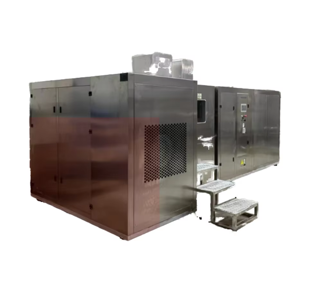
PV Blowing Sand And Dust Test Chamber
Category:Battery Safety Tester

Introduction
Photovoltaic Module Dust and Sand Blowing Test Chamber is an environmental reliability testing system designed to simulate high-dust and sand-laden conditions caused by natural or artificial disturbances. The chamber is mainly used to evaluate the sealing integrity, structural reliability, and optical performance degradation of photovoltaic modules under dust and sand erosion. By precisely controlling particle size, dust concentration, airflow velocity, and temperature, the equipment enables dust blowing, sand blowing, and dust deposition tests under repeatable conditions, providing reliable test data for photovoltaic applications in deserts, Gobi regions, transportation corridors, and other harsh environments.
Application
Evaluation of dust-proof and sand-proof sealing performance of photovoltaic modules and photovoltaic glass
Environmental adaptability testing of photovoltaic modules in desert, Gobi, arid, and high wind-sand regions
Durability assessment of coating layers and encapsulation layers of photovoltaic modules under sand erosion
Research and validation testing for new photovoltaic materials and encapsulation structures
Reliability verification of power equipment and outdoor electrical devices in dusty and sandy environments
Environmental adaptability testing of aerospace equipment and special-purpose systems under wind-sand conditions
Standards
(1)GB/T 2423.37-2006 Environmental Testing – Part 2: Test Methods – Test L: Dust and Sand Test
(2)GJB 150.12A-2009 Laboratory Environmental Test Methods for Military Equipment – Part 12: Dust and Sand Test
(3)IEC 60068-2-68 Environmental Testing – Part 2-68: Tests – Test Lb: Dust and Sand
(4)IEC 61300-2-27 Fibre Optic Interconnecting Devices and Passive Components – Basic Test and Measurement Procedures – Part 2-27: Dust Test
Parameters
| Item | Technical Specification |
|---|---|
| Working chamber size | Approx. 1000 × 1000 × 1000 mm (W × H × D) |
| Overall dimensions | Approx. 6500 × 2400 × 3400 mm (subject to actual equipment) |
| Temperature range | RT ±10 to 70 ℃ |
| Humidity range | ≤30% RH (display only, not adjustable) |
| Fine dust particle size | ≤75 μm |
| Coarse dust particle size | ≤150 μm |
| Horizontal dust/sand blowing wind speed | 1.5–29 m/s, continuously adjustable |
| Dust blowing concentration | 10.6 g/m³ ±7 g/m³ |
| Dust blowing wind speed | 1.5–8.9 m/s |
| Sand blowing concentration | 0.18 ±0.15 g/m³ / 1.1 ±0.3 g/m³ / 2.2 ±0.5 g/m³ |
| Sand blowing wind speed | 18–29 m/s |
| Sand blowing duration | 90 min (extendable) |
| Airflow type | Horizontal laminar flow |
| Sample size | 300 × 300 mm |
| Sample quantity | 3 pieces |
| Hua stone powder dosage | 2–5 kg/m³ (25 kg standard supply) |
| Power supply | AC 380 V ±10%, three-phase five-wire system, 80 A air circuit breaker |
Features
Horizontal laminar airflow design ensures uniform dust distribution and high test repeatability
Separate pre-treatment chamber and test chamber airflow circulation structure realistically simulates natural wind-sand environments
Multi-stage testing modes including dust blowing, sand blowing, and dust deposition for complex environmental simulation
Real-time dust concentration monitoring with automatic compensation to maintain stable test conditions
Inner and outer chambers constructed from high-grade stainless steel for corrosion and abrasion resistance
Supports high-temperature dust and sand blowing conditions for extreme photovoltaic environment testing
PLC and touchscreen intelligent control system with flexible parameter settings and intuitive operation
Accessories
(1)Dust circulation fan (all-plastic centrifugal fan)
(2)Dust collection box
(3)Vacuum system (vacuum pump, pressure regulating valve, suction nozzle, connecting pipes)
(4)Dust storage tank (for Hua stone powder)
(5)Metal mesh screen (wire diameter 50 μm, spacing 75 μm)
(6)Dust concentration meter with analog signal feedback to PLC
(7)Heating system (316 stainless steel heating elements)
(8)LED lighting system (high-intensity top illumination)
(9) Observation window with electrically heated anti-fog film
Maintenance Information
Regularly clean the dust circulation system, dust storage tank, and collection box to prevent accumulation and blockage
Inspect fans, heating elements, and airflow channels periodically to ensure stable airflow performance
Check seals, observation windows, and electrical connections for wear or aging
Replace dust powder and filters according to usage frequency and test standards
Perform calibration of wind speed and dust concentration measurement systems as required by test protocols
FAQ
What is the main purpose of the Photovoltaic Module Dust and Sand Blowing Test Chamber?
The chamber is designed to simulate dust- and sand-laden environments to evaluate the sealing performance, structural reliability, and optical degradation of photovoltaic modules. By controlling dust particle size, concentration, wind speed, and temperature, the equipment reproduces conditions commonly found in deserts, Gobi regions, and high wind-sand areas, allowing reliable assessment of photovoltaic module durability before field deployment.
Why is horizontal laminar airflow used in this test chamber?
Horizontal laminar airflow ensures uniform distribution of dust and sand particles across the sample surface. This airflow structure minimizes turbulence and concentration fluctuations, improving test repeatability and consistency. It also better reflects natural wind-sand movement, making the test results more representative of real environmental exposure conditions.
Can the chamber perform both dust blowing and sand blowing tests?
Yes. The chamber supports dust blowing, sand blowing, and dust deposition tests. Each stage can be conducted under independently controlled wind speed, concentration, and temperature conditions, allowing comprehensive simulation of complex environmental scenarios.
How is optical performance degradation evaluated after testing?
Optical performance degradation is evaluated by measuring the photovoltaic module’s light transmittance before and after the test. The attenuation rate is calculated by comparing the two measurements, providing a quantitative assessment of the impact of dust and sand erosion.
If you're ready to take the next step, Leave your message below and we’ll reply soon. 20+ years of manufacturing & export experience, a partner you can trust.