Roof-Mounted Photovoltaic Module Fire Test Apparatus
Category:Flammability Tester

Introduction
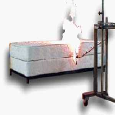
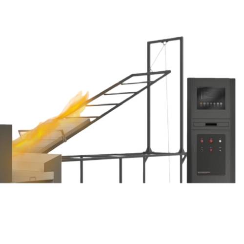
The Roof-Mounted Photovoltaic Module Fire Test Apparatus is a specialized testing system developed in accordance with GB/T 30735-2014 for evaluating the external fire performance of roof-mounted photovoltaic modules and roofing products. Based on test principles derived from ENV 1187 (t1 method) and ISO 12468-1. the apparatus simulates different fire exposure conditions such as wind influence and thermal radiation. It provides standardized test methods for assessing the external reaction to fire of roof systems and roof coverings, supporting fire safety evaluation of photovoltaic installations on roofs.
Application
The test apparatus is suitable for fire performance evaluation of roofing systems and photovoltaic installations under external fire exposure conditions. Typical applications include:
External fire reaction testing of roof-mounted photovoltaic modules
Fire performance evaluation of roof coverings and roofing assemblies
Assessment of building-integrated photovoltaic (BIPV) systems
Combustion behavior testing of roof construction materials
Fire safety research related to renewable energy installations
Type testing and compliance verification in certification and testing laboratories
Standards
The apparatus is designed to meet the requirements of the following standards:
(1) GB/T 30735-2014 – Test Method for Reaction to External Fire of Roofs and Roof Coverings
(2) ENV 1187: t1 – Test Methods for External Fire Exposure to Roofs
(3) ISO 12468-1:2013 (Method B) – Fire Performance of External Roofs and Roof Coverings — Part 1: Test Methods
(4) ISO 12468-1:2013 (Method C) – Fire Performance of External Roofs and Roof Coverings — Part 1: Test Methods
(5) UL 1703: multi-family and hotel room individual dwelling unit smoke detection monitors: electric signal detection of house dust;
(6) UL 790: standard method of fire test for roof covering materials;
(7) ASTM e 108-04: standard method of fire test for roof covering materials;
(8) NFPA 256: fire test of roof deck.
(9) IEC 61730-2 Appendix b: fire tests on PV modules.
Parameters
| Item | Specification |
|---|---|
| Radiant Panel Radiation Surface | 600 mm × 600 mm |
| Wood Crib Fire Gas Combustion Device | 1 set |
| Test Specimen Rack Angle | Adjustable, 0–50° |
| Air Duct Material | SUS304 stainless steel |
| Air Duct Thickness | 2 mm |
| Fan Airflow Capacity | Max. 250 m³/min |
| Fan Power | 5.5 kW |
| Fan Frequency Control | 3-phase 380 V, 5.5 kW |
| Air Duct Adjustable Angle | 0–35° |
| Impeller Anemometer | 3 units |
| Wind Speed Accuracy | 0.1 m/s |
Features
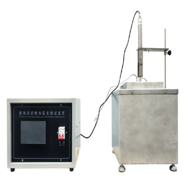
Frame-type structure for combustion and specimen holding systems, providing high mechanical stability.
Independent control cabinet and gas supply cabinet design, facilitating laboratory layout and improving operational safety.
Supplied with a compact stainless steel tube burner for wood shavings combustion tests.
Burner equipped with a silicon nitride igniter and UV flame detector, ensuring reliable ignition and real-time flame monitoring to prevent gas leakage.
Imported high-precision rotameter and branded pressure gauges for accurate control of fuel gas flow, combined with solenoid valves for automatic gas shutoff at the end of tests.
Specimen support frame constructed from welded metal square tubes and angle steel, ensuring rigidity during testing.
Adjustable specimen inclination angle using pneumatic actuation, allowing convenient push-button operation.
Fine honeycomb grille installed in the upper air duct and coarse honeycomb grille at the outlet to stabilize airflow.
Air duct angle adjustment driven by a ball screw and servo motor, enabling automatic and precise positioning.
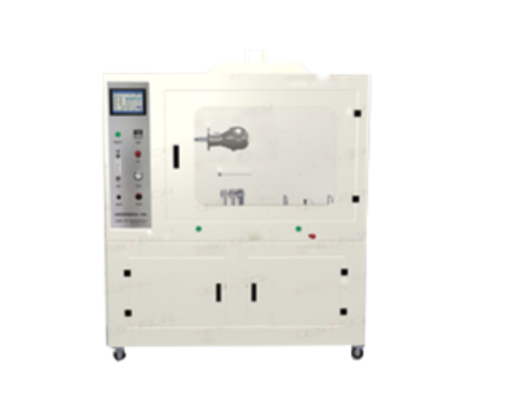
Computer and dedicated software control the entire test process, ensuring convenient operation and reliable safety management.
Accessories
(1) Radiant panel assembly
(2) Wood crib fire gas combustion device
(3) Stainless steel tube burner
(4) Specimen support rack
(5) Air duct system with adjustable angle
(6) Centrifugal fan and frequency control unit
(7) Impeller-type anemometers
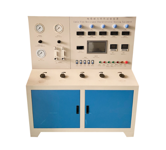
(8) Control cabinet and gas supply cabinet
(9) Computer and professional test software
Maintenance Information
Routine inspection of the burner, gas pipelines, solenoid valves, and flame detection system is recommended to ensure safe operation. The airflow system, including the fan, air duct, and honeycomb grilles, should be checked periodically for cleanliness and proper alignment. Moving components such as the specimen rack adjustment mechanism and air duct angle drive system should be maintained to ensure smooth operation. Electrical and control systems should be verified regularly according to laboratory safety procedures.
FAQ
1. What is the main purpose of this fire test apparatus?
The apparatus is designed to evaluate the external reaction to fire of roof-mounted photovoltaic modules and roofing products. By simulating fire exposure conditions such as thermal radiation and wind influence, it assesses how roof systems behave when subjected to external fire sources. The test results are used as an important reference for fire performance classification in accordance with GB/T 30735-2014 and related international standards.
2. Which test methods can be simulated using this system?
The system supports three fire exposure conditions defined in GB/T 30735. Method A corresponds to the t1 test method in ENV 1187. while Methods B and C correspond to the test methods specified in ISO 12468-1. These methods simulate different external fire scenarios by adjusting parameters such as radiant heat intensity, wind speed, and specimen inclination.
3. How is airflow controlled and measured during testing?
Airflow is generated by a high-capacity fan with frequency conversion control, allowing continuous adjustment of wind speed. The air duct angle is adjustable, and airflow velocity is measured using three impeller-type anemometers with an accuracy of 0.1 m/s, ensuring stable and repeatable wind conditions throughout the test.
4. What safety features are included in the combustion system?
The combustion system is equipped with a silicon nitride igniter and a UV flame detector to ensure stable ignition and continuous flame monitoring. In addition, solenoid valves automatically shut off the gas supply when the test ends, significantly reducing the risk of gas leakage and improving overall operational safety.
If you're ready to take the next step, Leave your message below and we’ll reply soon. 20+ years of manufacturing & export experience, a partner you can trust.