Single Wires and Cables Burning Tester
Category:Flammability Tester

Introduction
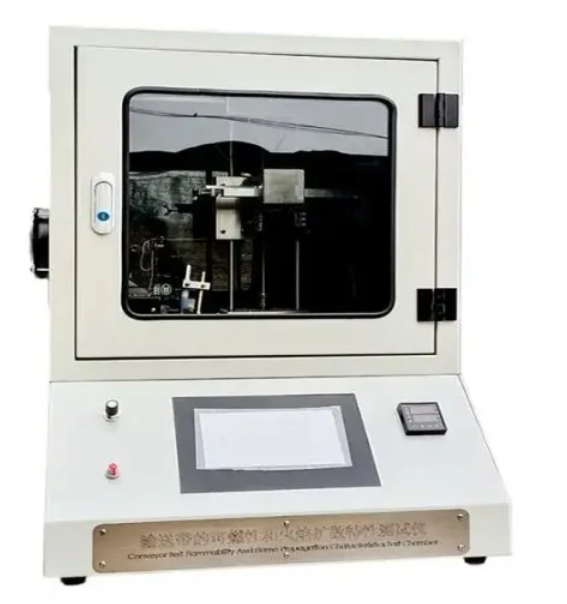
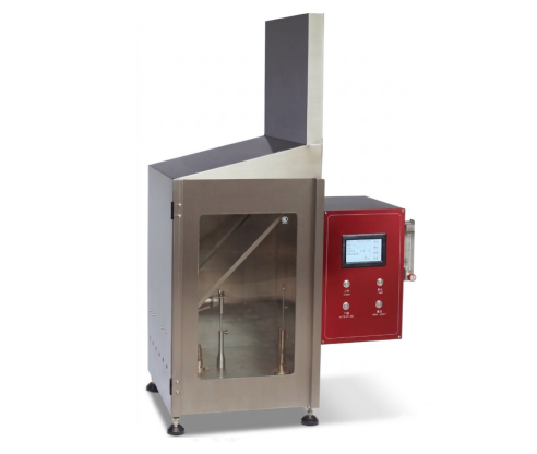
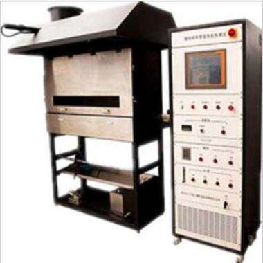
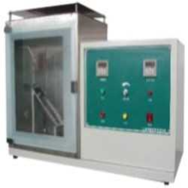
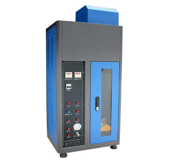
The Single Wire Cable Burning Tester is a precision flammability test system designed to assess the flame-retardant performance of single wires and cables under controlled laboratory conditions. It provides stable flame generation, accurate sample positioning, and automated monitoring for repeatable and reliable results. The instrument is widely used in electrical, electronics, and appliance industries to ensure product compliance with international safety standards.
Application
(1) Flammability testing of single wires and cables with conductor diameters >8 mm (cross-sectional area >0.5 mm²).
(2) Flammability testing of single wires and cables with conductor diameters <8 mm (cross-sectional area <0.5 mm²).
(3) Research and development of flame-retardant wire and cable materials.
(4) Quality control and inspection in manufacturing of wires, cables, and associated electrical components.
(5) Testing components of household appliances, low-voltage electrical appliances, lighting equipment, motors, power tools, electrical instruments, and connectors.
(6) Certification testing to meet international and national flame-retardancy standards.
Standards
(1) IEC 60332 – Tests on electric and optical fiber cables under fire conditions.
(2) GB/T 19666-2005 – Flame retardant performance of single wires and cables.
(3) GB 12972 – Test method for burning characteristics of wires and cables.
(4) GB 13033 – Vertical flame test for insulated wires and cables.
(5) MT 818 – Military standard for electrical wire flammability.
(6) MT 386 – Standard for wire and cable flame testing.
(7) ISO 5656 – International method for flame testing of electrical cables.
Technical Parameters
| Parameter | Specification |
|---|---|
| Burner Inner Diameter | Φ9.5 mm ± 0.5 mm |
| Test Inclination Angle | 45°, beam movable back and forth |
| Flame Height | 20 mm ± 2 mm – 190 mm ± 1 mm, adjustable |
| Flame Time | 0–999.9 s ± 0.1 s, adjustable |
| Combustion Gas | 95% propane gas (or liquefied petroleum gas) |
| Gas Supply | User-supplied high-purity propane or LPG |
| Tested Wire/Cable Length | 600 ± 25 mm |
| Burner Power | 1 kW |
| Supply Voltage | 220 V / 50 Hz |
| Gas Flow | 0–1 L/min |
| Air Flow | 1.5–15 L/min |
| Box Material | Steel with electrostatic spraying |
| Dimensions (L × W × H) | 60 × 45 × 156 cm |
Features
(1) Stable Bunsen burner flame with adjustable height (20 mm – 190 mm) for precise testing.
(2) Movable test beam with 45° inclination for accurate positioning relative to cable diameter and thickness.
(3) Programmable flame duration (0–999.9 s) for repeatable test cycles.
(4) Supports high-purity propane gas or liquefied petroleum gas as combustion source.
(5) Suitable for wires and cables of 600 ± 25 mm length.
(6) Durable electrostatic sprayed steel construction for long-term laboratory use.
(7) Easy-to-operate controls for adjusting gas and airflow rates.
(8) Compact dimensions for laboratory integration (L × W × H: 60 × 45 × 156 cm).
Accessories
(1) Bunsen burner assembly with flame height adjustment.
(2) Adjustable test beam with 45° inclination.
(3) Gas and air flow control valves.
(4) Sample holder for wire/cable mounting.
(5) Safety protection components (emergency stop, flame shield).
(6) Instruction manual and calibration certificate.
Test Procedures
Install the test sample (wire or cable, 600 ± 25 mm) onto the sample holder.
Adjust the test beam to 45° inclination relative to the sample.
Set the flame height according to the standard or test protocol.
Connect and regulate the combustion gas (propane or LPG) and airflow rates.
Initiate the flame and begin the timer for the required exposure duration.
Observe the sample and record the combustion behavior according to applicable standards.
Remove the sample safely after the test and evaluate the flame-retardant performance.
Maintenance Information
(1) Regularly clean the burner tip and sample holder to prevent residue buildup.
(2) Inspect gas and air flow lines for leaks and proper operation.
(3) Ensure electrostatic spraying surface remains intact to prevent corrosion.
(4) Calibrate flame height and timing mechanisms periodically to maintain accuracy.
(5) Store the instrument in a dry, ventilated environment when not in use.
(6) Follow all safety guidelines when handling flammable gases and during testing.
If you're ready to take the next step, Leave your message below and we’ll reply soon. 20+ years of manufacturing & export experience, a partner you can trust.