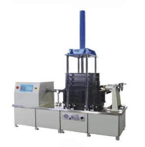
Geosynthetic Direct Shear Drawing Friction Tester
Category:Material strength tester
Introduction
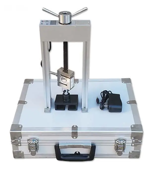
The friction characteristics of the interface of sand/geotextile were determined by testing the contact surface of standard sand/geotextile. This instrument is suitable for all geotextiles and related products. The instrument adopts high-precision servo motor.
By testing the pull-out friction resistance of the geosynthetic material and the surrounding soil, the pull-out resistance characteristics of the geosynthetic material were determined. It is suitable for soil of various soil properties and states and various types of geotextiles, geomembranes, geotextiles and geogrids.
Specification:
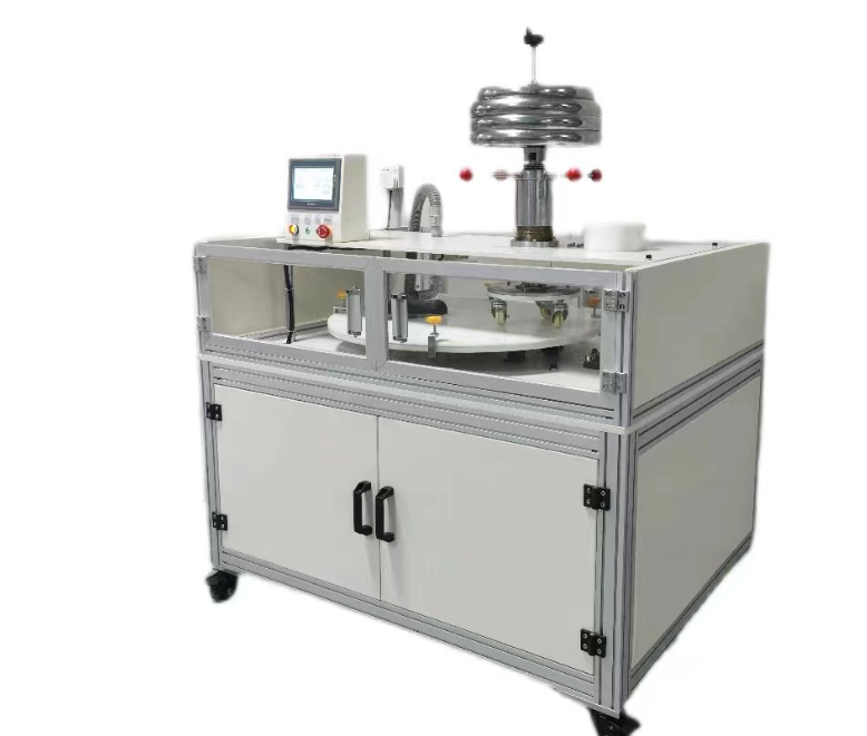
For direct shear test, adopt detachable drive unit, which can be moved from one shear box to another, allowing the testing of one sample while another sample is being prepared in a separate box.
For pullout test, the box is removable of a constant rate controlled by the servo motor; it is as same as moving box in direct shear test.
The direct shear test machine consists of servo motor, load cell, control panel, transducer, readouts for the sensors, etc.
The drive system is mounted on a wheeled frame to allow for easy separation from the sample box.
The box has low friction linear bearings when moving.
Digital readout for each test and can be connected to PC for data analysis.
Application
The geosynthetic materials direct shear and pull-out friction testing system is primarily used to test the pull-out friction resistance between geosynthetic materials (such as geotextiles, geomembranes, geogrids, etc.) and the surrounding soil, as well as the friction characteristics of these materials under direct shear conditions.
Material performance evaluation: It tests the friction and pull-out performance of geosynthetic materials under specific conditions to evaluate their stability and durability in practical applications.
Engineering material selection: It allows for the comparison of the friction and pull-out performance of different geosynthetic materials to select the most suitable material for engineering needs.
New material development: In the development of new geosynthetic materials, this system can serve as an important tool for performance evaluation, helping researchers optimize material formulations and processes.
Standard:
Direct shear test:
IS0 12957.1: Geosynthetics – Determination of friction characteristics – Part 1: Direct shear test
GB/T 17635.1-1998: Geotextiles and geotextile-related products – Determination of friction characteristics – Part 1: Direct shear test
JTG E50 T1129: Test method for direct shear friction of geosynthetics in highway engineering (corresponding to JTG E50 T1129)
SL/T 235: Specification for test and measurement of geosynthetics
ASTMD 5321: Standard Test Method for Determining the Coefficient of Soil and Geosynthetic or Geosynthetic and Geosynthetic Friction by the Direct Shear Method
Pull test :
JTG E50 T1130: Test method for pull-out resistance of geosynthetics in highway engineering (corresponding to JTG E50 T1130)
Parameters:
| Description | Details |
|---|---|
| Shear box sizes | 300 x 300 x 200mm; 600 x 600 x 300mm; 600 x 600 x 300mm Under the shear box: 300 x 300 x 200mm; 800 x 600 x 300mm; 800 x 600 x 300mm |
| Drawing box sizes | 300 x 300 x 340mm; 600 x 400 x 500mm; 600 x 400 x 500mm |
| Loading mode | Servo cylinder loading; Hydraulic loading; Hydraulic loading |
| Normal pressure | 0 – 250kPa; 50 – 300kPa (customizable) |
| Static load | 50 – 400kPa |
| Dynamic load | 50 – 300kPa |
| Horizontal drive mode | Servo cylinder; Servo motor; Hydraulic drive |
| Maximum horizontal force | 30kN; 50kN; 100kN |
| Horizontal load accuracy | 0.50% |
| Straight shear drawing speed | 0.1 – 10mm/min; 0.1 – 10mm/min; 0.3 – 10mm/min |
| Direct shear displacement | 0 – 100mm |
| Drawing displacement | 0 – 150mm |
| Displacement resolution | 0.01mm |
| Return speed | 1 – 50mm/min |
| Power supply | AC220V 50Hz |
| Overall dimensions | 2400 * 700 * 2000mm; 2900 * 850 * 3400mm; 1500 * 900 * 1800mm |
Features:
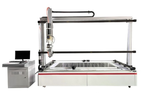
Direct shear drawing test system is an integrated machine with two functions of direct cutting and drawing, as long as by changing a small amount of tooling fixtures, two test functions can be achieved:
Computer upper computer software controls the test process, direct shear and drawing interface friction integration into one, software autonomy is strong, can independently set the experimental conditions of mainstream standards at home and abroad, applicable to mainstream national standards, and can independently complete data processing, to achieve full data export, easy to study the relationship between shear stress and displacement of samples and time, is a comprehensive interface friction test system;
The horizontal loading device adopts servo electric cylinder to realize full digital speed closed-loop control, which has the advantages of stable speed, wide speed range and high positioning accuracy, and the stretching speed can be set arbitrarily.
The normal loading device is realized by manual hydraulic or automatic electric cylinder, which is convenient and reliable, and the pressure is stable. The pin connection technology can quickly and simply change the clamp required for testing;
It has a variety of hardware and software protection measures such as overload and over-travel to ensure the safe and reliable operation of the equipment.
Accessoriess
Shear box
Vertical loading device
Horizontal loading device
Tensile and compressive force sensor
Displacement sensor, etc.
FAQ
1. What is the difference between the “Direct Shear” and “Pull-out” test in this machine?
Direct shear measures the friction along a horizontal plane where the soil and geosynthetic meet, while the pull-out test measures the resistance of a material being pulled out from between two layers of compacted soil. This machine allows you to perform both on one platform.
2. Why is servo motor control superior to hydraulic drive for horizontal motion?
Servo motors provide a much more stable and consistent speed (down to 0.1 mm/min) without the “pulsing” sometimes found in hydraulic systems. This is critical for capturing the precise peak and residual strength of the interface.
3. Can I test large-aperture geogrids with this system?
Yes, by selecting the larger box options (e.g., 600mm or 800mm), you can ensure that the geogrid apertures are sufficiently represented within the test area to provide statistically significant results.
4. How does the machine handle different soil types like clay or coarse sand?
The system is designed for a wide range of normal pressures (up to 300-400kPa). You can adjust the compaction method and loading rate to accommodate the drainage and consolidation characteristics of various soil types.
5. Is the data export compatible with third-party analysis software?
Yes, the software supports full data export (typically in CSV or Excel format), making it easy for you to import force-displacement curves into external geotechnical modeling software.