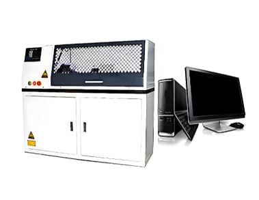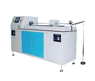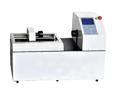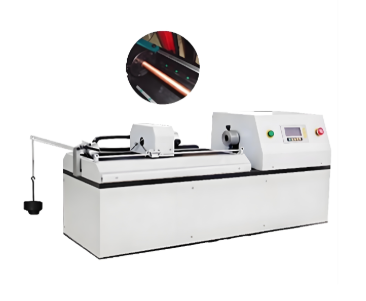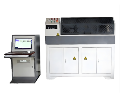
Camshaft Torsional Fatigue Testing Machine
Category:Torsion Testing Machine
Factory Direct
Stable Performance
Intl. Standards
Tech Support
Fast Delivery
Global Shipping

Introduction
The Camshaft Torsional Fatigue Testing Machine consists of a loading system, transmission system, digital data acquisition and processing system, and computer measurement, control, and display system.
Application
The Camshaft Torsional Fatigue Testing Machine is suitable for static torsional mechanical performance testing of camshafts and various camshaft components, including mechanical camshafts, double overhead camshafts (DOHC), single overhead camshafts (SOHC), and combined assemblies.
Test Functions
The machine adopts a Windows-based Chinese operating platform and supports multiple control modes for torque, torsion angle, and deformation.
It uses a graphical Windows operating system interface, allowing users to set the display screen and operation panel. The system supports setting of test speed and various control parameters, real-time display of basic test results, real-time display of related curves during the test process, and system diagnosis with diagnostic result display.
The entire system adopts a full digital AC servo control system and digital data acquisition and processing system. A photoelectric encoder is used to measure and acquire the torsion angle of the specimen.
Applicable Standards
The Camshaft Torsional Fatigue Testing Machine complies with the following standards:
GB/T 2611 — General Requirements for Testing Machines
GB/T 10128 — Metallic Materials — Torsion Test Method at Room Temperature
JB/T 9370 — Technical Conditions for Torsion Testing Machines
GB/T 3075 — Metallic Materials — Fatigue Testing — Axial Force-Controlled Method
ISO 18338 — Metallic Materials — Torsion Test at Ambient Temperature
Technical Specifications
1. Axial Force Test
(For tensile testing, our company provides professional camshaft pull-out force and tensile testing machines. Please contact our sales representative for details.)
a. Apply the specified axial load and check whether the cam lobe has any axial displacement relative to the shaft tube. If axial displacement occurs, the specimen is considered unqualified.
b. Continue loading until axial displacement occurs between the cam lobe and the shaft tube. Record the failure force F at the time of failure.
2. Static Torque Test
a. Apply the specified circumferential torque and check whether relative rotation occurs between the cam lobe and the shaft tube. If relative rotation occurs, the specimen is considered unqualified.
b. Continue loading until relative rotation occurs between the cam lobe and the shaft tube. Record the failure torque M at the time of failure.
3. Dynamic Torque Test
a. Apply dynamic torque loading (sine/cosine waveform).
b. Number of cycles: 8.3 × 10⁶ cycles.
If you're ready to take the next step, Leave your message below and we'll reply soon. 20+ years of manufacturing & export experience, a partner you can trust.